Testing Your Microphone (INMP441)
Test and verify the INMP441 digital I2S microphone with your ESP32 to capture clean audio samples before sending them to AI speech-to-text services.
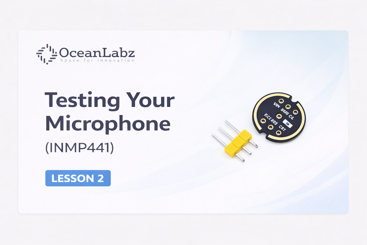
In Part 1, we covered the big-picture architecture of your AI voice assistant and introduced the hardware involved.
Now it's time to test the first crucial piece: your microphone! Before you record audio or send it to any AI service, you must verify that the mic is correctly wired and that the ESP32 can receive real audio data via I²S.
#Why This Matters
Unlike analog mics, the INMP441 is a digital MEMS microphone that communicates via the I²S protocol.
That means instead of reading voltages from a pin like a typical analog mic, you need to configure ESP32’s I²S peripheral to read digital audio samples.
If this step fails, the entire voice assistant won’t be able to hear anything — so this lesson ensures your “ears” work properly.
#What You’ll Need
| Component | Purpose |
|---|---|
| INMP441 Microphone | Captures sound digitally |
| ESP32 Board | Reads audio over I²S |
| Breadboard + Jumper Wires | For connections |
| USB Cable | To program and power the ESP32 |
#Wiring the INMP441 to ESP32
Connect your microphone using the standard I²S pins for this project.
| INMP441 Pin | ESP32-S3/S3 Mini | ESP32 Pin | ESP32-C3 | Function |
|---|---|---|---|---|
| VDD | 3V3 | 3V3 | 3V3 | Power |
| GND | GND | GND | GND | Ground |
| SD | GPIO 41 | GPIO 35 | GPIO 21 | Serial Data (Audio In) |
| SCK (BCLK) | GPIO 40 | GPIO 33 | GPIO 1 | Bit Clock |
| WS (LRCK) | GPIO 39 | GPIO 32 | GPIO 0 | Word Select (Left/Right Clock) |
| L/R | GND | GND | GND | Channel Select (Ground = Left Channel) |
Critical Note: The L/R pin determines if the mic outputs to the Left or Right channel. Connecting it to GND selects the Left channel, which is required for our code configuration.
#What Is I²S?
I²S (Inter-IC Sound) is a communications protocol designed just for audio.
Instead of sending bits like SPI or Serial, I²S sends continuous digital audio frames with:
- BCLK — bit clock (timing)
- LRCLK / WS — left-right channel select
- DOUT — digital audio data
In this lesson, your ESP32 will listen to this stream from the mic.
#The Test Code
Copy and paste this code into your Arduino IDE. This sketch initializes the I²S driver and prints the volume levels to the Serial Monitor.
[object Promise]#4. How to Verify
- Upload the code to your ESP32-S3.
- Go to Serial Monitor.
- Set the baud rate to 115200.
- Clap or Speak: You should see spikes in values corresponding to the noise you make.