ESP32 RGB LED Module with Arduino IDE
## Introduction The KY-016 RGB module allows you to produce a variety of colors by mixing red, green, and blue light. It has built-in resistors for each color, making it easy to connect directly to the ESP32. By using PWM on three GPIO pins, the ESP32 can control brightness levels and create smooth
#Introduction
The KY-016 RGB module allows you to produce a variety of colors by mixing red, green, and blue light.
It has built-in resistors for each color, making it easy to connect directly to the ESP32.
By using PWM on three GPIO pins, the ESP32 can control brightness levels and create smooth color transitions.
#Required Components
- ESP32 Board
- KY-016 RGB LED module
- Jumper wires
- Breadboard (optional)
#Pinout

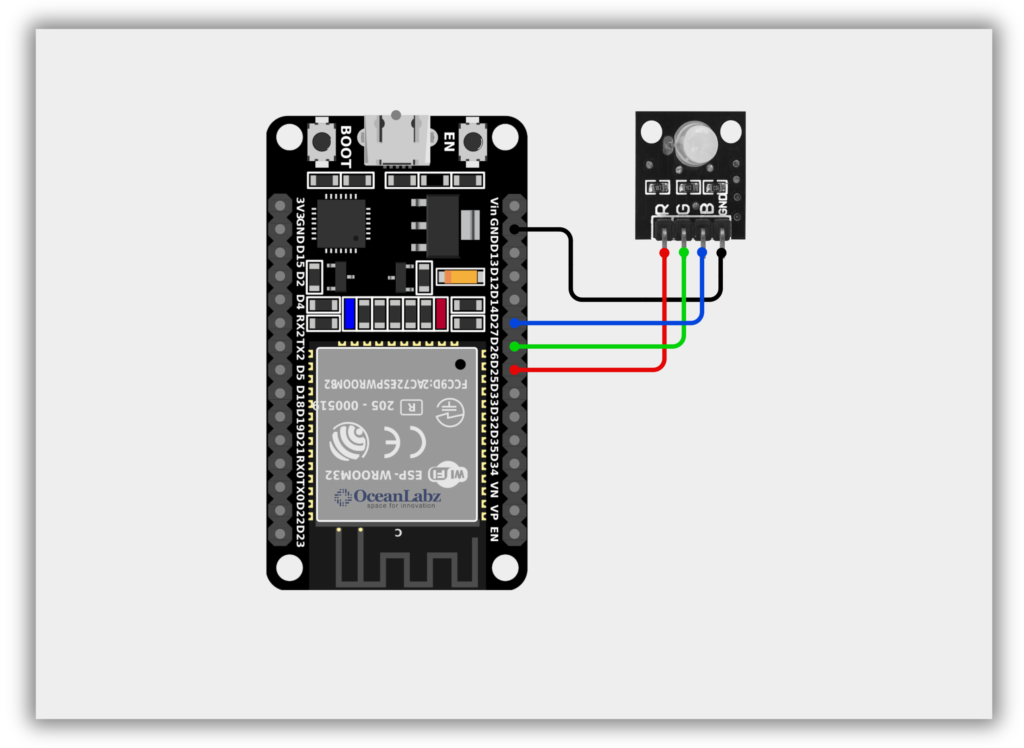
#Circuit Diagram / Wiring
- RGB (GND) → ESP32 GND
- RGB (RED) → ESP32 25
- RGB (GREEN) → ESP32 26
- RGB (BLUE) → ESP32 27
#Code / Programming
/* Filename: esp32_rgb_led_pwm.ino Description: Cycle through RGB colors using PWM on ESP32 Author: www.oceanlabz.in Modification Date: 1/4/2025 */
// Define RGB pins const int redPin = 25; const int greenPin = 26; const int bluePin = 27;
// Define PWM channels const int redChannel = 0; const int greenChannel = 1; const int blueChannel = 2;
void setup() { // Setup PWM channels: channel, frequency, resolution (8-bit) ledcSetup(redChannel, 5000, 8); ledcSetup(greenChannel, 5000, 8); ledcSetup(blueChannel, 5000, 8);
// Attach channels to GPIOs ledcAttachPin(redPin, redChannel); ledcAttachPin(greenPin, greenChannel); ledcAttachPin(bluePin, blueChannel); }
void loop() { // Red setColor(255, 0, 0); delay(1000);
// Green setColor(0, 255, 0); delay(1000);
// Blue setColor(0, 0, 255); delay(1000);
// Yellow setColor(255, 255, 0); delay(1000);
// Cyan setColor(0, 255, 255); delay(1000);
// Magenta setColor(255, 0, 255); delay(1000);
// White setColor(255, 255, 255); delay(1000);
// Off setColor(0, 0, 0); delay(1000); }
// Set RGB color void setColor(int red, int green, int blue) { ledcWrite(redChannel, red); ledcWrite(greenChannel, green); ledcWrite(blueChannel, blue); }
#Explanation
- The KY-016 RGB module has three color channels (Red, Green, Blue) that can be controlled using PWM signals.
- The ESP32 uses
ledcWrite()on PWM-capable GPIO pins to mix colors and create visual effects. - This setup allows you to display various colors by adjusting brightness levels for each LED component.
#Troubleshooting
- If colors appear incorrect, check the RGB pin connections (R, G, B may be mislabeled or reversed).
- Make sure you're using PWM-capable pins and have correctly configured
ledcSetup()andledcAttachPin(). - For common anode modules, reverse the logic (use
255 - value) insetColor()to get correct brightness.
#Project 1: Interactive RGB LED Color Controller Using Push Buttons
#Introduction
In this project, an RGB LED is controlled using a push button connected to the ESP32.
A single press changes the LED color, a double press activates a smooth breathing effect, and a long press turns the LED off.
The LED cycles through colors like red, green, and blue with smooth transitions for visual appeal.
This beginner-friendly ESP32 project demonstrates GPIO input handling and PWM-based LED control for dynamic lighting.
#Required Components
- ESP32 Board
- KY-016 RGB LED module
- Switch Module
- Jumper wires
- Breadboard
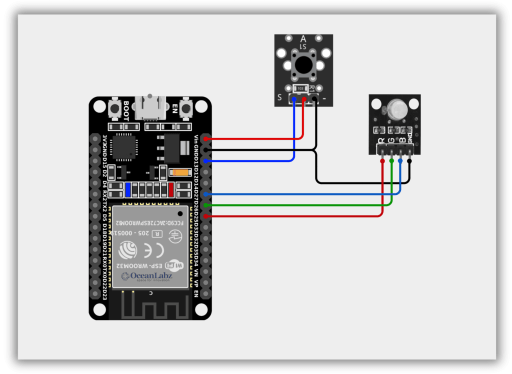
#Circuit Diagram / Wiring
RGB with ESP32
RGB (GND) → ESP32 GND
RGB (RED) → ESP32 25
RGB (GREEN) → ESP32 26
RGB (BLUE) → ESP32 27
Push Button with ESP32
- BUTTON (VCC) → ESP32 5V,3V
- BUTTON (GND) → ESP32 GND
- BUTTON (SINGNAL) → ESP32 GPIO 13
#Code / Programming
/* Filename: esp32_rgb_button_control.ino Description: RGB LED control with single, double, and long button press using ESP32 and PWM Author: www.oceanlabz.in Modification Date: 1/4/2025 */
#define BUTTON_PIN 13 // Valid GPIO for button input #define RED_PIN 25 // PWM-capable GPIO for Red LED #define GREEN_PIN 26 // PWM-capable GPIO for Green LED #define BLUE_PIN 27 // PWM-capable GPIO for Blue LED
// PWM channels #define RED_CHANNEL 0 #define GREEN_CHANNEL 1 #define BLUE_CHANNEL 2
unsigned long lastPressTime = 0; unsigned long pressDuration = 0; unsigned long debounceTime = 200; unsigned long doublePressInterval = 500; unsigned long longPressDuration = 2000;
bool fadeEffect = false; int colorIndex = 0;
// RGB color list int colors[][3] = { {255, 0, 0}, // Red {0, 255, 0}, // Green {0, 0, 255}, // Blue {255, 255, 0}, // Yellow {0, 255, 255}, // Cyan {255, 0, 255}, // Magenta {255, 255, 255} // White };
void setup() { Serial.begin(115200); pinMode(BUTTON_PIN, INPUT_PULLUP);
// Set up PWM channels ledcSetup(RED_CHANNEL, 5000, 8); // 5 kHz, 8-bit resolution ledcSetup(GREEN_CHANNEL, 5000, 8); ledcSetup(BLUE_CHANNEL, 5000, 8);
// Attach GPIO pins to PWM channels ledcAttachPin(RED_PIN, RED_CHANNEL); ledcAttachPin(GREEN_PIN, GREEN_CHANNEL); ledcAttachPin(BLUE_PIN, BLUE_CHANNEL);
setColor(0, 0, 0); // Turn off LED at start }
void loop() { static bool lastButtonState = HIGH; bool buttonState = digitalRead(BUTTON_PIN);
if (buttonState == LOW) { pressDuration = millis() - lastPressTime; } else if (lastButtonState == LOW && buttonState == HIGH) { if (pressDuration > longPressDuration) { fadeEffect = false; setColor(0, 0, 0); Serial.println("Long Press: LED Off"); } else if (pressDuration > debounceTime) { unsigned long currentTime = millis();
[object Promise]}
lastButtonState = buttonState;
if (fadeEffect) { fadeColors(); } }
void fadeColors() { for (int i = 0; i <= 255; i++) { setColor(i, 0, 255 - i); delay(5); } for (int i = 255; i >= 0; i--) { setColor(i, 255 - i, 0); delay(5); } for (int i = 0; i <= 255; i++) { setColor(255 - i, i, 0); delay(5); } for (int i = 255; i >= 0; i--) { setColor(0, i, 255 - i); delay(5); } }
void setColor(int red, int green, int blue) { ledcWrite(RED_CHANNEL, red); ledcWrite(GREEN_CHANNEL, green); ledcWrite(BLUE_CHANNEL, blue); }
#Explanation
- The project uses a single button to control an RGB LED on an ESP32 with three actions: single press (change color), double press (start/stop fading), and long press (turn off).
- The LED supports multiple static colors and a dynamic breathing/fade effect using ESP32's PWM channels.
- This interactive design teaches button press detection, RGB color control, and PWM fading using minimal components.
#Troubleshooting
- LED Not Lighting? Check wiring and ensure the RGB LED common cathode/anode is correctly connected and not reversed.
- Button Not Responding? Make sure the button is connected to GPIO 13 and using
INPUT_PULLUPmode with a proper ground connection. - PWM Flickering or No Color? Confirm the RGB pins are on PWM-capable GPIOs (25, 26, 27) and not used by flash or other reserved functions.