ESP32 PIR Motion with Arduino IDE
## Introduction The PIR (Passive Infrared) sensor detects motion by sensing changes in infrared radiation. It outputs a digital HIGH signal to the ESP32 when motion is detected, and LOW when idle. Commonly used in security systems, motion-activated lights, and automation projects. In this tutorial,
#Introduction
The PIR (Passive Infrared) sensor detects motion by sensing changes in infrared radiation.
It outputs a digital HIGH signal to the ESP32 when motion is detected, and LOW when idle.
Commonly used in security systems, motion-activated lights, and automation projects.
In this tutorial, we’ll connect a PIR sensor to the ESP32 and detect motion events.
#Required Components
- ESP32 Board
- PIR Motion Sensor
- Jumper wires
- Breadboard (optional)
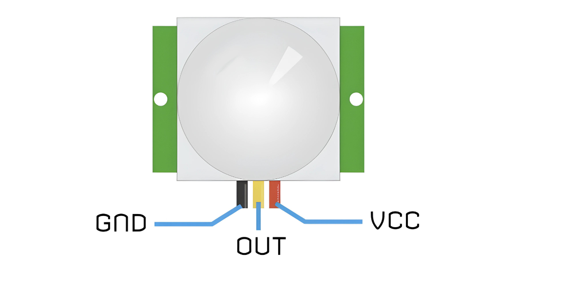
#Pinout
#Circuit Diagram / Wiring
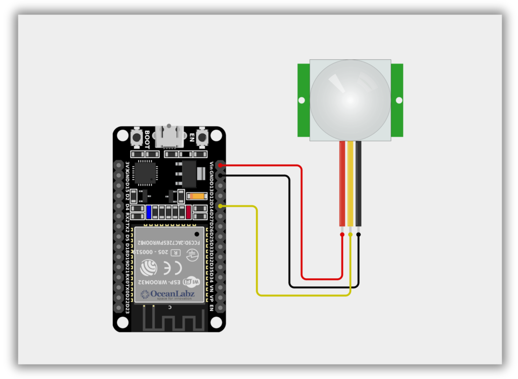
- PIR VCC → VIN/5V (ESP32)
- PIR GND → GND (ESP32)
- PIR OUT → 14 (ESP32)
#Code / Programming
/* Filename: pir_motion_sensor.ino Description: Detects motion using a PIR sensor connected to ESP32 and prints status via Serial Monitor. Author: www.oceanlabz.in Modification Date: 1/4/2025 */
#define PIR_Pin 14 // Use GPIO14 or any other available digital pin
void setup() { Serial.begin(115200); // Use a higher baud rate for ESP32 pinMode(PIR_Pin, INPUT); // Set PIR pin as input Serial.println("PIR Sensor Initialized"); }
void loop() { int val = digitalRead(PIR_Pin); // Read PIR sensor value
if (val == HIGH) { Serial.println("Motion Detected"); } else { Serial.println("No motion detected."); }
delay(1000); // Delay for stability }
#Explanation
- The PIR sensor detects motion by sensing changes in infrared radiation from moving objects.
- It sends a HIGH signal to ESP32 when motion is detected and LOW when idle.
- ESP32 reads this digital signal to trigger actions like alerts, lights, or automation tasks.
#Troubleshooting
- If motion is never detected, wait 30–60 seconds after powering up for the PIR sensor to stabilize.
- Ensure the OUT pin is connected to a proper digital GPIO, like GPIO14 (avoid boot-sensitive pins like GPIO0, 2, or 15).
- If false triggers occur, adjust the PIR sensor’s sensitivity and delay knobs to filter out noise.
#Project 1: ESP32-Based PIR Motion Detection Alarm System
#Introduction
This project is a PIR Motion Detection Alarm System using an ESP32, a PIR sensor, a buzzer, and an LED.
It detects motion using the PIR sensor and immediately alerts with a buzzer sound and LED light.
The ESP32 also prints real-time movement status to the Serial Monitor for monitoring.
Ideal for home security and automation, it’s a simple way to learn motion detection and output control.
#Required Components
- ESP32 Board
- PIR Motion Sensor
- Buzzer
- LED with Resistor 220 Ohm
- Jumper wires
- Breadboard
#Circuit Diagram / Wiring
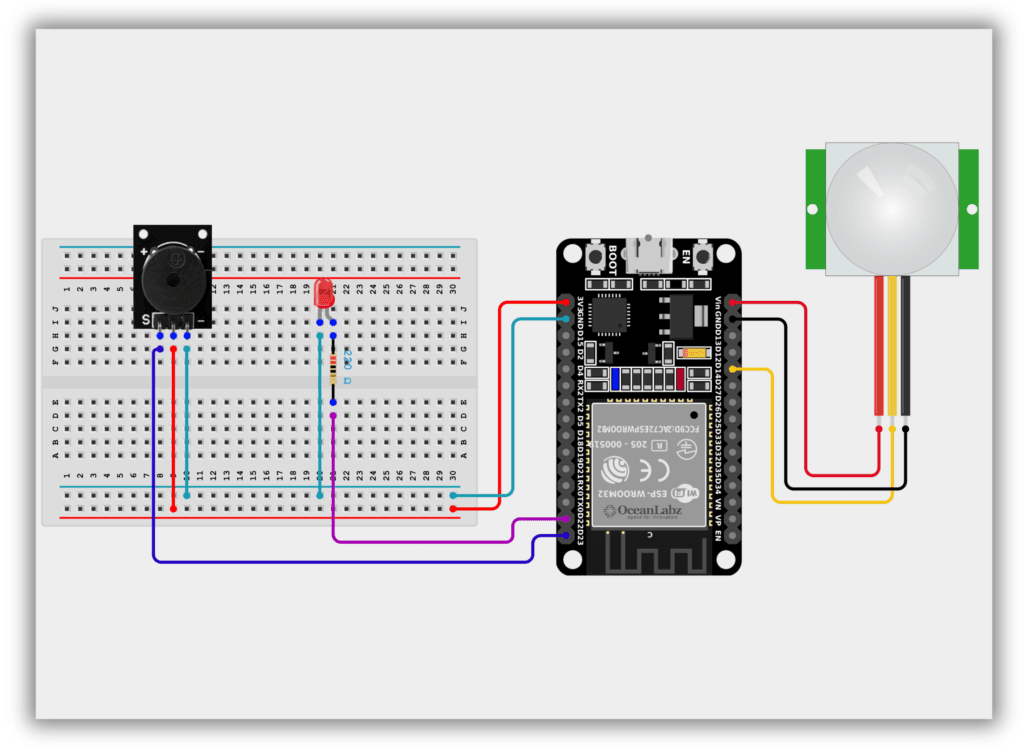
- PIR VCC → VIN/5V (ESP32)
- PIR GND → GND (ESP32)
- PIR OUT → GPIO 14 (ESP32)
- Buzzer VCC → VIN (ESP32)
- Buzzer GND → GND (ESP32)
- Buzzer SINGNAL → GPIO 23 (ESP32)
- Connect the LED anode to GPIO 22 (via a 220-ohm resistor) and cathode to GND.
#Code / Programming
/* Filename: PIR_Motion_Detection_Alarm_System.ino Description: Uses a PIR sensor to detect motion and triggers a buzzer and LED using ESP32. Author: www.oceanlabz.in Modification Date: 1/4/2025 */
int Buzz = 23; // GPIO 23 for Buzzer int LED = 22; // GPIO 22 for LED int PIR = 14; // GPIO 21 for PIR Sensor int val = 0; // Initialize value
void setup() { pinMode(Buzz, OUTPUT); pinMode(LED, OUTPUT); pinMode(PIR, INPUT); Serial.begin(115200); // ESP32 uses higher baud rates }
void loop() { val = digitalRead(PIR); // Read PIR sensor value
if (val == HIGH) { digitalWrite(LED, HIGH); // Turn LED ON digitalWrite(Buzz, HIGH); // Turn Buzzer ON Serial.println("Movement Detected"); } else { digitalWrite(LED, LOW); // Turn LED OFF digitalWrite(Buzz, LOW); // Turn Buzzer OFF Serial.println("Movement not Detected"); }
delay(200); // Small delay for stability }
#Explanation
- The PIR sensor detects motion and sends a HIGH signal to the ESP32's input pin.
- When motion is detected, the ESP32 turns ON the buzzer and LED as visual and audible alerts.
- Serial Monitor prints real-time status updates: either "Movement Detected" or "Movement not Detected".
#Troubleshooting
- No Output on Serial Monitor: Ensure correct COM port and baud rate (
115200) in Arduino IDE. - False Triggering: Power cycle the PIR sensor after uploading code; wait 30–60 seconds for it to stabilize.
- No LED or Buzzer Response: Check wiring and GPIO pin numbers; confirm your ESP32 board supports the assigned pins.